|
Back to C64DTV Stuff
C64DTV Color Fix
Use this as much as you want, but please give proper credits.
Watch this space!
/Daniel Kahlin (tlr)
Color Problem
Symptoms
- White is not a proper white, just grey.
- Luminance seems to change in uneven steps, but a higher luminance
value is still more bright than a lower value.
There are excellent shots of this by Roland T—gel here.
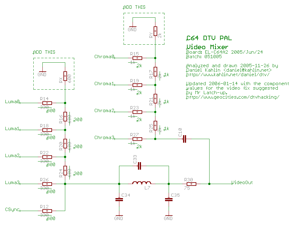
Suggested fix (2006-01-14) from an authorative source (Mr. Latch-up/Irej): here
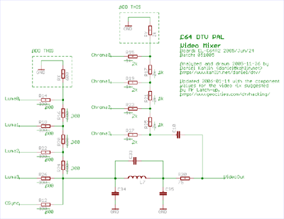
Schematic of the video mixer with the authorative fix shown.
Click for a larger view.
The matter is discussed in-depth in this thread on the dtvhacking forum.
Details
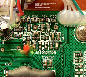
A close up shot of the video-mixer in my C64DTV PAL
Click for a larger view.
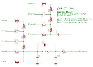
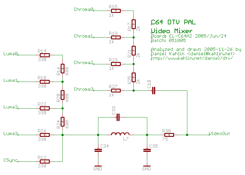
A schematic of the same video-mixer (look mom, no output buffer! :/ )
Click for a larger view.
(Thanks to Nicolas Welte for determining which REFDES' are Luma3/CSync respectively.)
Note that, contrary to my first thoughts, not having an output buffer could actually be an improvement in output quality. The video-mixer no longer requires a supply voltage. This supply voltage could introduce moire problems if too noisy.
Also it is two resistors and one transistor less + no requirements for supply filtering around the video- and audio-mixers.
Cause
As seen in my schematic above the video-mixer does not have an open-emitter
buffer stage for any of the signals. (the original reference schematic has this buffer)
Chrominance seems to work acceptably as it uses 1k and 2k resistors for
its conversion.
Luminance on the other hand uses values 330ohms and 680ohms, and it appears
have a too low signal level, and uneven steps.
Theories
- The output of the C64DTV ASIC does not handle that kind of load smoothly. Due to how the resistor ladder is constructed, the load is much higher on the more significant bits. This could result in the uneven steps we see.
unlikely.
- The 3% difference in nominal resistance makes the ladder skewed in the way seen. This could result in the uneven steps.
unlikely.
- The amplitude of the Luma signal is low because the resistor ladder has too high impedance. It wouldn't be possible to lower the resistances in the
Luma DAC, because the output of the C64DTV ASIC couldn't deliver the load.
possibly.
- As MadModder pointed out, the ladder could have the resistors swapped, thus making the steps look strange.
Very likely, see below for my simulations!
Possible fix (2005-11-27)
My guess for a complete fix is:
Luma:
(Simulations below.)
- Change R14,R18,R22,R26 to 300ohms. (was 330ohms)
- Change R12 (CSync) to 300ohms. (was 330ohms)
(This one might not be necessary, it changes the black-level)
- Change R16,R20,R24 to 150ohms. (was 680ohms)
- The icing on the cake: Connect a 300ohms resistor from the point between R16/R14 to ground. (Courtesy of Nicolas Welte)
Chroma:
(These doesn't seem to be as necessary as the other ones.)
- Change R15,R19,R23,R27 to 2k (was 1k)
- Change R17,R21,R25 to 1k (was 2k).
- Connect a 2k resistor from the point between R17/R15 to ground.
If you have the time and skill, please do these one at a time and if possible send a report with screen shots here.
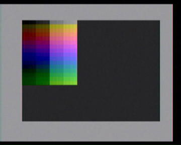
Run this to display a 256 color display like below: displaytest.prg.
(It will reread the userport config every time it is started, so you can test on the fly if you know what you are doing.)
Note: Modifications are always done on your own risk, and will definately void your warranty!
Tests
- 2005-11-27: Nicolas Welte tested swapping some of the resistors in the Luma DAC.
(R18 <-> R16, R22 <-> R20, R26 <-> R24)
This seems to produce fully acceptable output in the menu of winter games.
my comments: this will fix the Luma problem for all bits except Luma0, but the sync level will probably be wrong.
- 2005-11-27: Nicolas Welte tested setting R14,R18,R22,R26 to 680ohms, and R16, R20, R24 to 330ohms, but then added a crucial fix: 680ohms connected from the point between R14/R16 and ground. The full range of colors are then available. Although a little bit too dark.
my comments: I think the output brightness might be affected in a good way if R12 is changed to 680ohms aswell. In the DTV-Manual it says: "Drives high during non sync times to set black level."
- 2005-11-29: Suschman swapped some of the resistors in the Luma DAC.
(R18 <-> R16, R22 <-> R20, R26 <-> R24)
- 2005-11-29: Michael B—hmer tried the full fix simulated below with good results. Unfortunately Michael hasn't been able to test with the 256 color test program. (he only had his DTV for 2 days, so no IEC connector yet)
(Luma: R16, R20, R24 = 150ohms, R14, R18, R22, R26 = 300ohms, R12 = 300ohms (CSync), between R14/R16 and ground = 300ohms
Chroma: R17, R21, R25 = 1kohms, R15, R19, R23, R27 = 2kohms, between R15/R17 and ground = 2kohms)
- 2005-12-03: Michael B—hmer sent me 256-color shots of the mod above.
The Video Signal (or why is the screen too dark?)
Now if we do the second Luma resistor test above, the screen is still to dark, why?
See below...
National Instruments has a good page about the video signal.
The signal levels are given in IRE, and I translated this into volts below.
The signal for PAL should be (in relative voltages):
| Sync: | -0.307V |
| Blanking Level: | 0V |
| Black Level: | 0V |
| White Level: | 0.714V |
The signal for NTSC should be (in relative voltages):
| Sync: | -0.276V |
| Blanking Level: | 0V |
| Black Level: | 0.054V |
| White Level: | 0.714V |
The original circuit
R14,R18,R22,R26 and R12 to 330ohms, and R16, R20, R24 to 680ohm.
| Sync Level: | 0V1 |
| Black Level: | 0.362V2 (0.328V measured) |
| White Level: | 0.854V2 (0.812V measured) |
1 Luma0-3 is low during CSync low
2 effective range 0.492V (0.484V measured) (should be 0.714V)
Linearity is terrible!
Now we look at the levels we get when setting R14,R18,R22,R26 to 680ohms, and R16, R20, R24 to 330ohm plus 680ohms connected from the point between R14/R16 and ground.
The modded Luma DAC with R12=330ohms (CSync) will give the range: (again relative)
| Sync Level: | 0V 1 |
| Black Level: | 0.395V 2 |
| White Level: | 0.757V 2 |
1 Luma0-3 is low during CSync low
2 effective range 0.362V (should be 0.714V)
The modded Luma DAC with R12=680ohms (CSync) will give the range: (relative)
| Sync Level: | 0V 1 |
| Black Level: | 0.219V 2 |
| White Level: | 0.631V 2 |
1 Luma0-3 is low during CSync low
2 effective range 0.412V (should be 0.714V)
So how do we fix it?
R12 mainly affects the depth of the sync pulse, so we tweak that last.
The simulations below include the full output filter (L7=1.8u, C33=22p, C34=270p, C35=300p) but not possible voltage drop in the drivers.
The tweaked Luma DAC 300/150ohms: (relative)
When setting R14,R18,R22,R26 and R12 to 300ohms, and R16, R20, R24 to 150ohm plus 300ohms connected from the point between R14/R16 and ground.
| Sync Level: | 0V1 |
| Black Level: | 0.330V 2 |
| White Level: | 0.949V 2 |
1 Luma0-3 is low during CSync low
2 effective range 0.619V (should be 0.714V)
Much better! But this can be tweaked...
Note: Linearity can be almost perfect if you always mount R16,R20,R24 as two stacked (parallel coupled) resistors.
Note: If resistance values get to low, the output voltage of the
drivers will start to vary more and more dependant on the binary value.
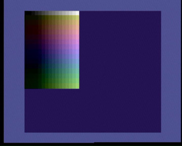
Screen grab of an affected PAL C64DTV
(Courtesy of Roland T—gel)
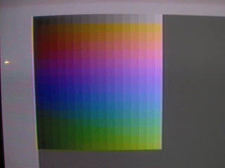
Screen grab of an original NTSC C64DTV
(Courtesy of Roland T—gel)
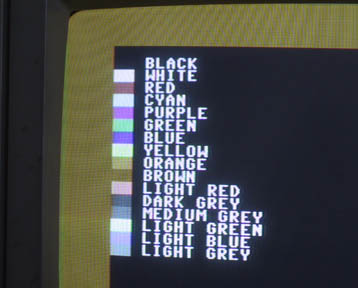
PAL C64DTV with the Luma DAC modified
(Courtesy of Nicolas Welte)
R14,R18,R22,R26 = 680ohms, R16,R20,R24 = 330ohms, 680ohms connected from the point between R14/R16 and ground.
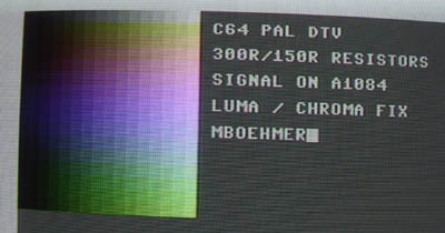
PAL C64DTV with the Luma/Chroma DACs modified
(Courtesy of Michael B—hmer)
R16,R20,R24 = 150ohms, R14,R18,R22,R26,R12 = 300ohms, between R14/R16 and ground = 300ohms, R17,R21,R25 = 1kohms, R15,R19,R23,R27 = 2kohms, between R15/R17 and ground = 2kohms
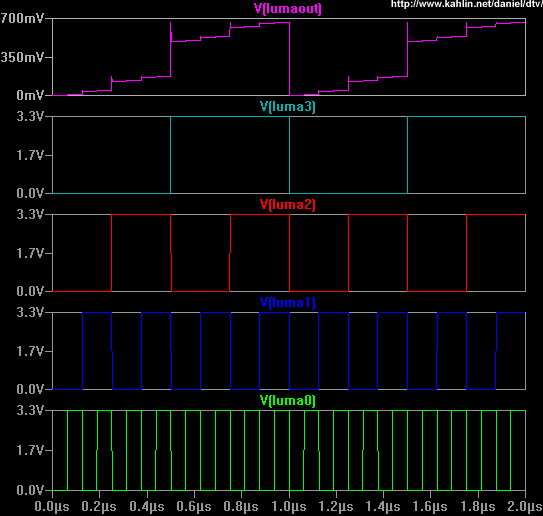
Simulations of swapped resistors in the luminance DAC
Original, with color problem. Looks familiar.
(Rload=75ohms, no filter, CSync held low, offset is wrong)
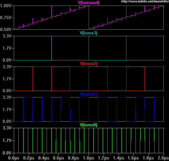
Resistors swapped back, Much better!
(Rload=75ohms, no filter, CSync held low, offset is wrong)

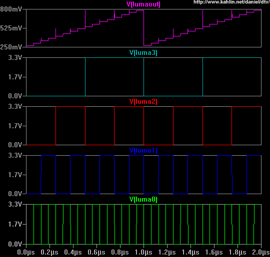
Resistors swapped back, with extra resistor to ground, Very good!
R14,R18,R22,R26=680ohms, R12=330ohms (CSync), R16,R20,R24=330ohms
(Rload=75ohms, no filter, CSync held high, offset is correct)
Resistors swapped back, with extra resistor to ground, Very good!
R14,R18,R22,R26=680ohms, R12=680ohms (CSync), R16,R20,R24=330ohms
(Rload=75ohms, no filter, CSync held high, offset is correct)
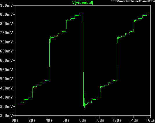
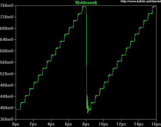
Original circuit Linearity is really terrible!
(Rload=75ohms, filter included (L7=1.8u, C33=22p, C34=270p, C35=300p), CSync held high, offset is correct)
R14,R18,R22,R26=330ohms, R12=330ohms (CSync), R16,R20,R24=680ohms
Resistors swapped back, with extra resistor to ground
(Rload=75ohms, filter included (L7=1.8u, C33=22p, C34=270p, C35=300p), CSync held high, offset is correct)
R14,R18,R22,R26=680ohms, R12=330ohms (CSync), R16,R20,R24=330ohms
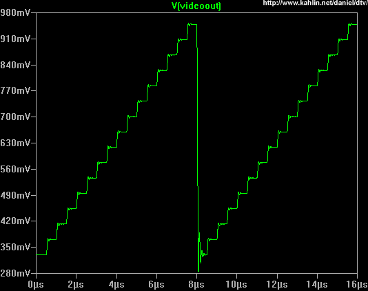
Tweaking the level... Pretty good, but still a bit too dark.
(Rload=75ohms, filter included (L7=1.8u, C33=22p, C34=270p, C35=300p), CSync held high, offset is correct)
R14,R18,R22,R26=300ohms, R12=300ohms (CSync), R16,R20,R24=150ohms
|

 kahlin
 net>.
net>.